
Overview
In this post I will show you how to utilize the SPI interface of the pico in order to send or receive data with NRF24L01+ transceivers. For the coding part we’ll use a micropython driver that is available in the micropython library on github, so we only have to write very little code.
Update 2021-06-13: Added if-branch to the nrf24l01test.py-File specific to the Pin-configuration and platform of the Pico. This is a crucial step, otherwise you’ll receive some error while testing
Update 2021-07-16: Added potential solution for the case that your transceivers fail to exchange messages – be sure to read the last section of this post.
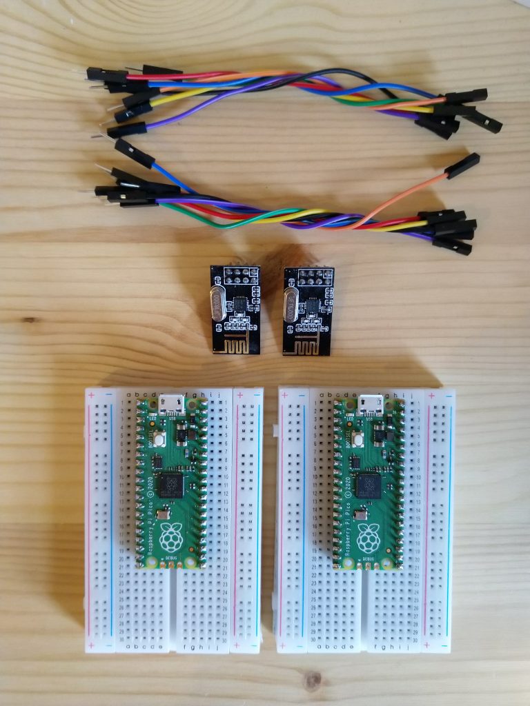
Which components do you need for this project?
- (2x) Raspberry Pi Pico that runs micropython with soldered header pins
- (2x) NRF24L01+ transceiver
- (2x) Breadboard
- Jumper wires
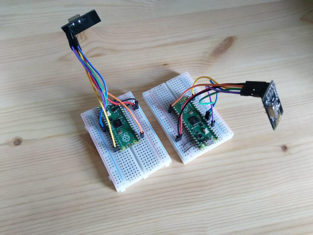
If you’ve got some F2F jumper wires, then the breadboard is not needed, however it will be easier to test the wiring when using one. Too see, in the end, whether our setup is working or not, we actually need to build the whole thing two times (where the first transceiver is configured as a receiver and the second one is configured as a transmitter).
About the NRF24L01+
It is a single chip transceiver which operates on the 2.4GHz ISM frequency band (between 2.400 and 2.4835GHz). It can be controlled via SPI and has some registers that we can write into in order to configure it, like e.g. set frequency channel, power output or air data rate. The latter one for example can be configured to use one of the following rates: 250 kbps, 1 Mbps or 2 Mbps. The chip can be used to transmit (TX mode) and to receive (RX mode). It can be operated between -40°C and +85°C and with its internal state machine it incorporates two different standby modes in order to keep the power consumption low whenever possible.
Implementation
If you’re ready, grab some coffee and start!
The wiring
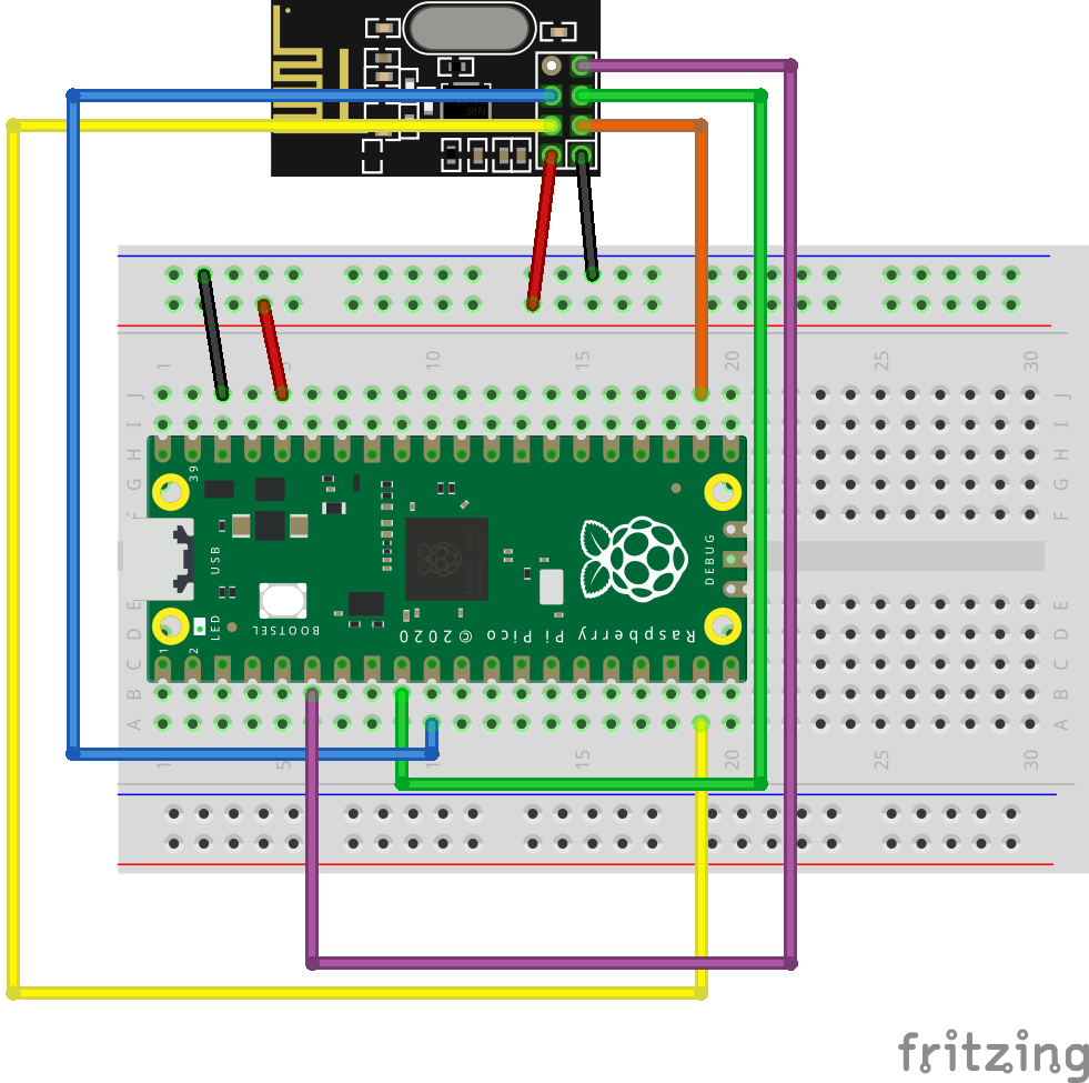
If we take a look into the official Raspberry Pi Pico Python SDK Documentation, we can find the default PIN setup for the SPI interface under section 3.7 SPI. Please keep in mind that the numbers in the default-column in the referenced section are referring to the GPIO Pin numbers and not to the physical Pin numbers. We can use this information to draw the following wiring diagram and table:
| Pico | NRF24L01+ |
|---|---|
| Pin 36 / 3V3 Out | VCC |
| Pin 38 / GND (or any other GND Pin) | GND |
| Pin 22 / GP17 | CE |
| Pin 19 / GP14 | CS |
| Pin 9 / GP6 | SCK |
| Pin 10 / GP7 | MOSI |
| Pin 6 / GP4 | MISO |
The code
For the next parts I will make use of the Thonny IDE which was already included with the Raspberry Pi OS that I installed on my Raspberry Pi 4. You of course can stick to the IDE or OS that you’re familiar with.
Luckily we don’t have to code everything from scratch. Instead we use a driver from the micropython drivers library, which can simply be obtained from their github project: nrf24l01.py. This piece of code does most of the work for us, we simply have to upload it to our pico’s filesystem in order to use it. If you do not already know how to do this, please follow some basic tutorial on how to use the pico first, before you proceed (like e.g. getting started with the pico).
If you’re using Thonny we can use both picos at the same time, however we first have to make sure that the IDE is configured correctly:
- By default Thonny only lets you open a single window, but we need two instances of the IDE running at the same time if we want to test our modules. To change that open up Thonny, click the Tools-Tab > Options… > Uncheck the box that says Allow only single Thonny instance.
- Open up another Thonny instance and plug-in both of your picos to your computer.
- Make sure that both of the shells are using the same interpreter type MicroPython (Raspberry Pi Pico). You can select the interpreter by clicking on the name of the current one beneath the shell tab.
- You’ll notice that on the second instance of Thonny you will receive an error message:
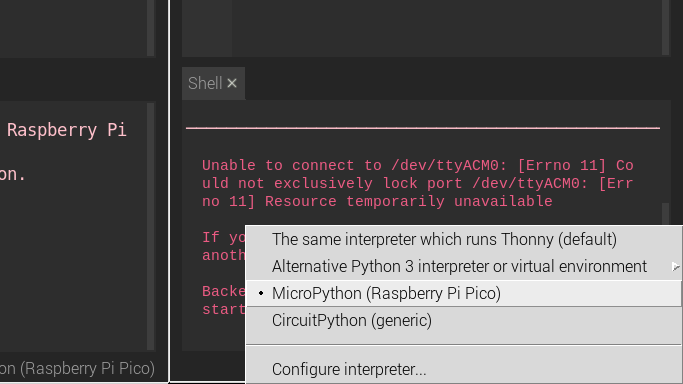
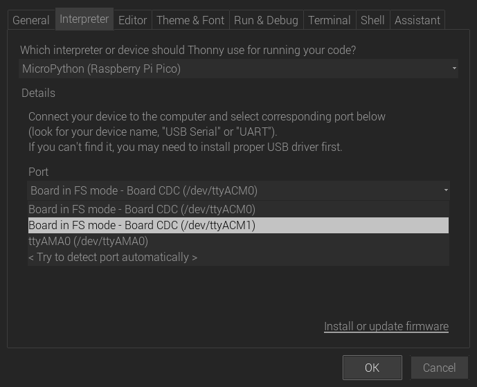
Which only means that the second instance of Thonny is trying to connect to the same pico that the first one is already connected to, which is not possible. To solve this issue, click the Tools-Tab in the Thonny instance that printed the error message > Options… > Click the Interpreter-Tab and change the Port to the name of the other Pico:
After saving the settings, we should now see both python REPL-shells running correctly.
To upload the driver to both of the picos, we can simply copy and paste the code that can be found in the github project (see the link above) into a new file for each of both instances. Then we save the files to both of our picos with the same name: nrf24l01.py.
Testing
Once we’ve set up our picos with the driver we can now proceed to test them together. In the next few steps we will use one of the transceivers as a receiver and the other one as a transmitter.
In the same github project that was mentioned in the section above, we can find another file called nrf24l01test.py which does this for us. This is great! In order to test our modules we don’t have to care about the details and the configuration of the transceivers. However, if you want to use them for your own purposes/projects, then maybe you should take a close look on how the driver actually works and how to configure it to fit your needs.
The only thing we have to make sure is that we need to specify the SPI Pin-configuration for the Pico specifically within this file. So first copy and paste the code into new files for each of the IDE instances. Then change the Pin configuration part (at the beginning of the file, beneath the import statements) to the following:
if usys.platform == "pyboard":
    cfg = {"spi": 2, "miso": "Y7", "mosi": "Y8", "sck": "Y6", "csn": "Y5", "ce": "Y4"}
elif usys.platform == "esp8266":  # Hardware SPI
    cfg = {"spi": 1, "miso": 12, "mosi": 13, "sck": 14, "csn": 4, "ce": 5}
elif usys.platform == "esp32":  # Software SPI
    cfg = {"spi": -1, "miso": 32, "mosi": 33, "sck": 25, "csn": 26, "ce": 27}
elif usys.platform == "rp2":  # PI PICO
    cfg = {"spi": 0, "miso": 4, "mosi": 7, "sck": 6, "csn": 14, "ce": 17}
else:
    raise ValueError("Unsupported platform {}".format(usys.platform))
We’ve just added the if-branch […]elif usys.platform == “rp2”:[…] to the code, so that it’ll also consider the pico platform and our specific SPI Pin-configuration. Save both of the files to each of the picos with the name nrf24l01test.py. In the next step we create another file for each of the picos. In the first one we simply write the following code:
import nrf24l01test

nrf24l01test.master()
Save this file to the pico on which you want to use the transceiver as a transmitter. You can name it however you want, but keep in mind that if you save it as main.py it’ll execute the code as soon as the pico is powering up. In the second file (on the other Thonny instance) we write the code:
import nrf24l01test

nrf24l01test.slave()
Save this file to the other pico in order for it to use the transceiver as a receiver.
To test the devices, we first start the receiver/slave by hitting Run in the according Thonny instance. If no error occurred we can proceed to also start the transmitter/master in the other Thonny instance. We should now be able to see the script doing its tests.
Et voilà, if the two transceivers succeed to send packets to each other, we can now use them for further projects.
Code is running without error, but no success in receiving messages?
Then you might want to try and set another configuration for the speed-setting on the transceivers. Initially in the constructor of the class NRF24L01 it is set to the SPEED_250K constant within the driver files: nrf24l01.py
...
class NRF24L01:
    def __init__(self, spi, cs, ce, channel=46, payload_size=16):
        ...
        # set rf power and speed
        # --> Change SPEED_250K to either SPEED_1M or SPEED_2M
        self.set_power_speed(POWER_3, SPEED_250K)
        ...
...
However, if you don’t want to change the actual driver code, you can use the same method “set_power_speed(power, speed)” of the same class after instantiating the objects within the nrf24l01test.py files. Make sure to also use the constants that have been defined in nrf24l01.py (SPEED_1M or SPEED_2M) when doing it that way.
Hey Man,
Thanks for the great tutorial.
Would it be possible to use a different pinout then the standard spi0 pinout?
I have all my wires hooked up to GP1 to GP5.
Hey Torac!
Thanks to your comment I’ve recognized that I haven’t mentioned the SPI-Pin configuration that we have to make in the ‘nrf24l01test.py’ – be sure to check out the update I made in the testing-section above, since you’ll also have to tweak the config in the code to solve your problem.
To answer your question: Yes we can use the second SPI-interface which the pico is providing to us, as the documentation also suggests. If you make the following changes to the wiring:
Pico | NRF24l01+
…
Pin 11 / GP8 –> MISO
Pin 14 / GP10 –> SCK
Pin 15 / GP11 –> MOSI
…
And the following changes to the code (File ‘nrf24l01test.py’ as described in the updated section):
...elif usys.platform == "rp2": # PI PICO
cfg = {"spi": 1, "miso": 8, "mosi": 11, "sck": 10, "csn": 14, "ce": 17}
...
Then you should be good to go 🙂
Just let me know if it didn’t work for you
Traceback (most recent call last):
File “”, line 3, in
File “nrf24l01test.py”, line 106, in slave
File “nrf24l01.py”, line 82, in __init__
OSError: nRF24L01+ Hardware not responding
I am getting error like this what should I do now!
Hey Abdul,
the error means that the driver code was not able to write into the setup-register of your transceiver. Are you sure that your wiring is correct and that the SPI-configuration in the code corresponds to this exact wiring?
If you already double-checked the wiring – it could also mean that maybe a header pin that is needed on your pico is not soldered correctly or poorly (you can check via multimeter or a simple LED+resistor). If all pins are working fine, then it could also mean that your transceiver is faulty (just to name a few causes that could lead to that problem).
Hey Man,
Thanks for the exelent tutorial!
I have a trouble – NO receiving messages:
Communication via the SPI interface is working. I write and read nrf registers. I try various configuration for the speed-setting, try various address and pipes. But no success in receiving messages also. NRF Modules are working, they working with NUCLEO board.
What could i be missing?
Thanks in advance!
Hey Dmitry,
thank you for your comment!
I can only try to guess here, since I have no experience with the board that you seem to be using. However, if the SPI interface is working fine and you can actually write to the registers of the NRF modules, but there are connections issues then those are the first things that come to my mind:
– Ensure that you use the correct addresses on both NRFs and the same Frequency setting
– Ensure that your board obtains power from a reliable power source (the NRF modules are finicky about power and noise when it comes to receive messages).
– You can try to add a small capacitor in between the VCC- and GND-Pins of the NRF modules to smoothen out the power line (something like 10μF should do). Please note that I haven’t actually tried this solution.
I cannot guarantee that this will solve it, but I hope this helps.
Thanks for this tutorial! It made getting my boards set up a snap- except I ran into the same problem Dmitry did. I tried every suggestion in the comments here (and every other thread I could find) trying to get my cheap-o NRF24L01+ boards working, and nothing recommended did the trick. I finally got things working, so I figured I’d post my solution. Hopefully it helps someone else.
In case it matters to your situation: my boards are a few feet apart. There’s minimal interference in my workshop. I tried changing the power and transmit speed, picked the best channel my WIFI scanner could give me, etc. I checked my voltage, and it was steady to within a 100th of a volt during transmission and reception. The best I could get was a few successful received messages on the agent, and no replies to the controller.
What finally fixed it for me was getting a set of these breakout boards: https://www.makerfocus.com/products/4pcs-nrf24l01-wireless-module-with-breakout-adapter-3-3v-regulator-on-board?_pos=1&_sid=61c6c6fca&_ss=r. They’re designed to use 5V power to regulate 3.3V, but on my Pico-to-Pico setup (which only produces 3.3V), they worked like a charm.
Hey! Thank you for posting your solution here, this is appreciated of course.
(Please note: Coffeebreakpoint.com cannot take any responsibility for the link in the comment above)
I had the same problem. Only once in a while a package would get through with the units cm apart. Added an additional capacitor, but still no luck. Added the breakout boards and at all works like a charm. Also a lone LM1117 does the trick. Maybe the power out of the pico has a ripple that interferes with these cheap boards?
Hello,
So i have followed the steps listed and am using the exact same code for 2 different picos one of the picos works as i tried both the transmitting and receiving code and it appears to be functioning well
the other one however i have set up the exact same for code and for wiring but now i get the error “Traceback (most recent call last):
File “”, line 3, in
File “nrf24l01test.py”, line 106, in slave
File “nrf24l01.py”, line 78, in __init__
OSError: nRF24L01+ Hardware not responding”
I tried swapping NRF24L01 modules between the two picos as maybe one was defective but the one still works fine with the swapped tranceivers
Any tips or advice would be greatly appreciated thank you
Hey Ben!
Thanks for using the comments!
Abdul actually had the same issue which he mentioned in the comments above. Have you already checked and tried out the suggestions that I gave as a reply there?
Hi Ben
The GitHub links to the .py files do not appear to work , probably my problem
Simon
Hi Simon!
Thank you for pointing this out. Problem was that the maintainers of the driver code removed the files from the current master branch, but luckily they tagged all the older micropython releases so that the files remain easy accessible. I updated the links so they should work again.
Have you successfully set up a mesh network with the Pico using the nRF24L01 transceivers? I’d like to move away from Arduino and start playing with Micropython / Circuitpython but I require a mesh network to communicate to numerous remote sensors.
Hi Mike!
No I haven’t done that and I also don’t know if there is a library or some tutorial already out there that covers your needs. But of course if you have the time you can take the code from here and build your own things on top of that. For example you could formulate a python dictionary with all your devices and their respective addresses. That way every instance knows the addresses of all the others. You could also define a special device with a certain address that is responsible for letting the other ones know about any knew devices in the network (much like a publish / subscribe model). There are many possibilities.
Hi!! I just followed your tutorial but I got blocked by this error
Traceback (most recent call last):
File “”, line 1, in
File “nrf24l01test.py”, line 24, in
ValueError: Unsupported platform rp2
I am actually using a raspberry pi pico W and I also added the section for the pico in the test file. Any help ?
Thanks
Hi Freddy!
Please try this in your Python-REPL shell:
import usys
print(“my platform is:”, usys.platform)
print(usys.platform == “rp2”)
This should give “True” if the platform is “rp2” and the correct “elif” – Branch should be working.
You can also just delete all of the if-branches in the “test”-File and just use your specific Pin-configuration (if you only use this setup of course), like this:
cfg = {“spi”: 0, “miso”: 4, “mosi”: 7, “sck”: 6, “csn”: 14, “ce”: 17}
Hello,
Thank you for this in depth tutorial. I was able to get the two boards sending packets but I was curious as to how to use this to send strings? I’m fairly new to data transmission, I’d appreciate any information/tutorials you can provide.
Thanks.
Hey Christopher,
thank you for the good question! Basically yes, we can send strings as well. It is just a bit more tricky if the string is not a fixed size: The transceivers are able to send a maximum of 32 Bytes with any single transmission. While doing that, they do not care much about what those Bytes mean to the code. You can set the payload-size while instantiating NRF24L01-objects (see Line 54 nrf2401l.py).
There are two important functions being called in the testing-script: Before sending data it is
struct.pack("ii", millis, led_state)which turns the two integers “millis” and “led_state” into a byte representation which the transceiver can handle (see Line 58 nrf2401ltest.py). The receiver of this data must however turn it back again into something that makes sense for it. In the test-script for example, it is unpacked again into two integers viamillis, led_state = struct.unpack("ii", buf)(see Line 115 nrf2401ltest.py).Now if you want to transmit a string you can send an integer first which defines the length of the string that is being attached in the payload, so that the receiver then knows how much bytes there are to unpack (see this stackoverflow post). Another way would be to always send strings with fixed lengths (then you can omit the integer that defines the length). There is also the possibility to just not send strings at all (depends of course if that is possible for your problem that you want to solve), which would be much easier, less error prone and less data needs to be transmitted. Maybe you can make a python dictionary that you can load onto both transceivers, where an id (an integer) is mapped onto a specific string that you then can further use on the receivers side. Then sender would only have to send a single integer id to let the receiver know which string it has to get from the dictionary.
If none of that works for you, let me know!
I’ve connected nrf24l01+ module with pico H. The nrf24l01test.py is configured for power_3,speed_2M. However, while testing the slave and master, only one module is working good for both master and slave, the other one is working only for master but not as slave. I’ve changed the nrf24l01+ module and checked again, but ended up with the same problem. Why is it that the same code is working for both as master and slave in one pico h but only master in the other? I swapped the nrf modules with the 2 pico h and tried but again ended the same problem. One module is working perfectly in master and slave configuration while the other is only working as master but not slave even though the code is same.
Pingback: Raspberry Pi Pico W and Bluetooth in Micropython. As easy as 123! - Coffeebreakpoint
LIke a number of other people I had trouble getting this to work. Like some other posters I got the OSError: nRF24L01+ Hardware not responding message. So I tried running the commands in repl, and finally got them to work. Long story short it seems the command to set up the nrf in the test file is not correct. In the version I downloaded It is:
“nrf = NRF24L01(SPI(cfg[“spi”]), csn, ce, payload_size=8)”
I changed it to:
“nrf = NRF24L01(SPI(cfg[“spi”], sck=Pin(cfg[“sck”]), mosi=Pin(cfg[“mosi”]), miso=Pin(cfg[“miso”])), csn, ce, payload_size=8)”
If these values are not specified for the SPI command, they default to:
“sck=18, mosi=19, miso=16”
not 6, 7, and 4 as shown in the “cfg” string.
Hope this helps.