
Overview
In this post I will show you how to quickly make use of analogue values on your Pico. This is one of the easier tasks, so we will not have to do much coding. First I will give a quick example that’ll showcase the usability of analogue values by doing pure electronics. After that I give another example on how to use such analogue values with the Raspberry Pi Pico while using Micropython. If you’re only interested in the Pico project, just jump straight to it.
Components needed for the electronics project
- 1x Rotary Potentiometer (in this project: one with 10k Ohm resistance)
- 1x Power Source (In this project: battery case with 4x AAA recharcheable Ni-MH batteries)
- 1x Breadboard
- 1x LED
- Some Jumper wires
- Some resistors
Components needed for the Pico project
- 1x Raspberry Pi Pico that runs micropython with soldered header pins
- 1x Rotary Potentiometer (in this project: one with 10k Ohm resistance)
- 1x Breadboard
- Some Jumper wires
Basic electronics project: Dimming an LED
This project is a rather simple one, but it showcases how analogue values can be used to do all kinds of different things that need variable input (no fixed values like digital signals). If you want to know more about the difference between analogue and digital signals, I can recommend you this post from Sparkfun.
To begin with the project we first need to set up the wiring on the breadboard. We will connect a power source to the potentiometer (or POT for short) in order to control the voltage across one of the three pins. For this project I will make use of four (in series) connected AAA recharcheable Ni-MH batteries with 1.2V each as the power source, which together are going to provide 4.8V when fully charged. The POT I have for this example needs the power and ground wires connected to the outer pins while the center one will provide the controlled output voltage. Please read the specs of the POT that you have at hand in order to correctly wire it.
So we will put the anode of our LED towards the center pin of the POT in order to use the controlled value of it. Next we have to make sure that we don’t exceed the max current limit that our LED can take by putting one or multiple resistors in series in the line of the cathode of the LED. We can use Ohm’s Law to calculate the minimum resistance that is needed. The LED that I’m using in this example has the limit on electric current at 20mA, please refer to the specs of the LED that you want to use, to make sure that you don’t damage it.
Ohm’s Law:
![\[ I = U/R\]](https://coffeebreakpoint.com/wp-content/ql-cache/quicklatex.com-8a54930d56d74946e4f758bf833334bf_l3.png "Rendered by QuickLaTeX.com")
![\[ R = U/I \Rightarrow R = 4.8~V/0.02~A \Rightarrow R = 240~Ohm\]](https://coffeebreakpoint.com/wp-content/ql-cache/quicklatex.com-1ed720b560697223e47ecccaa408dfc3_l3.png "Rendered by QuickLaTeX.com")
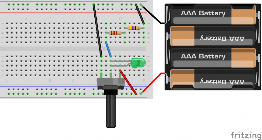
If the circuit is working, you should now see the LED get brighter or dimmer when rotating the POT. The value across the center pin of the POT will vary in the range between zero and the input voltage. Tip: If you switch power and ground pins on the POT it will reverse the effect of the rotation on the center pin.
The Pico project: LED blinking frequency
In this project I will show you how to read and use analogue values with the Pico. We will power the potientiometer (or POT for short) with our Pico and also collect the resulting value of it through an ADC-Pin (Analog to Digital Converter). In the coding part we will fetch the converted value of the ADC-Pin and use it to control the blinking frequency of the internal LED. Let’s start!
The wiring
The following table and diagram show how to wire the components on our breadboard:
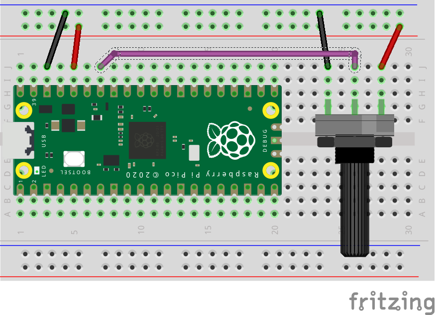
| Pico | Poti |
| Pin 36 / 3V3 Out | Right outer Pin |
| Pin 38 / GND (or any other GND Pin) | Left outer Pin |
| Pin 34 / GP28 / ADC2 | Center Pin |
Please refer to the specs of the POT that you want to use for this project in order to wire it correctly. Tip: if you swap the two outer pins on the POT it will reverse the effect of the rotation on the center Pin.
The code
We want to make the internal LED blink according to the output value of the POT. The ADC-Pin of the Pico translates the incoming voltage that is coming from the POT into a digital signal that we can then use within the code. The precision of the digital value is important here, so we can calculate the percentage of the voltage on the pin in contrast to the output voltage of the pico. That means that if we rotate the POT towards the max possible degree, this would give us either 0V or 3.3V across the center pin (depending on how you wired up the POT).
In my case this would mean that if I turn the POT all the way to the left I would get 0V and if I turn it all the way to the right I would get 3.3V of voltage across the center pin. However if we want to use this in the code, we need to use digital signals.
The ADC-Pins of the Pico converts those analogue values into digital ones with a precision of 16 bit. So we can fetch values by calling .read_u16() on our ADC-Pin within the code which will give us values in between 0 and the max value: 2^16-1. If we divide the actual value on the pin through the max value, we will get the percentage of it which is more usable in this case. The following code does all this and lets the internal LED of the pico blink in a frequency according to the rotation of the POT:
import machine
import utime
import math

pot_pin = machine.ADC(28) # POT-input on the Pico
led_pin = machine.Pin(25,machine.Pin.OUT) # internal LED of the Pico
max_val = math.pow(2,16)-1 # maximum value unsigned 'short' = 2^16-1

while True:
    pot_val = pot_pin.read_u16() # fetch the digital converted value
    pot_pct = pot_val/max_val # calculate percentage

    # Print for debugging
    print(str(pot_val) + " -> pct: " + str(pot_pct*100))
    led_pin.toggle()

    if pot_pct == 0: # avoid division through zero
        utime.sleep(1)
    else: # set frequency with max. 1/100 second and min. 1 second
        utime.sleep(1/(pot_pct*100))
If you run this code on your Pico, you should be able to control the blinking frequency of the internal LED by the rotation of the POT.
Pingback: Micropython POT class for quick and simple potentiometer interfacing - Coffeebreakpoint
Pingback: Want to move something? Here's how to use a Micro Servo with Micropython (Including easy code) - Coffeebreakpoint
if it’s a 12-bit ADC, why are we reading an unsigned 16-bit integer?
Hi Micheal,
that’s a good point, but there is a reason for this: Like you already mentioned, the RP2040s ADC Pins only have a precision of 12 bits, that means it can actually just “differentiate” the load on the Pin in the range of 0 to 4095 (a 12-bit unsigned integer).
However converting it into a 16-bit range via “read_u16()” is just the micropython way to generate code-compatibility to other Micropython devices (so that the code also works on other boards).
You can read it up on page 15 in the official Raspberry Pi Pico Python SDK.